Schiedel ICS
ICS is a Twin wall insulated chimney system for gas, oil, wood and multi-fuel. Available in 80 – 300mm internal diameter.
ICS is a Twin wall insulated chimney system for gas, oil, wood and multi-fuel. Available in 80 – 300mm internal diameter.
ICS is a twin wall insulated chimney system for use on open and closed stoves, open fires, residential and small commercial multi fuel appliances, with continuous operating temperatures up to 450°C and short firing up to 550°C.
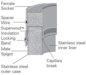
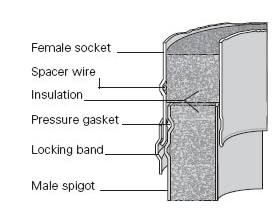
 ICS is converted into ICS Plus by adding a lip seal to each component with a male form on the liner (see ICS Plus diagram below). This creates a twin wall insulated chimney system designed for the new generation of condensing gas and oil appliances, with continuous operating temperatures up to 200°C, short firing up to 250°C, and positive pressure up to 200pa at the appliance outlet.
The video below shows how quickly and safely you can convert ICS to ICS Plus using a Viton gasket.
 For larger commercial and industrial applications of ICS in diameters 300mm to 700mm please refer to our separate sales brochure. For higher pressure applications up to 5000Pa e.g. generators, combustion and process equipment, please see the commercial brochure.
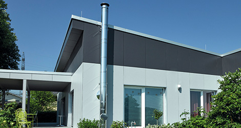
A multi-functional twin insulated venting system for use on a wide range of heating appliances, stand-by power engines, CHP and service ducting
| ICS | ICS Plus | ICS 5000 | |
| Fuel | Gas, Oil, wood, coal | Gas, oil | Diesel generators, gas, oil |
| Firing temp | 450°C | 200°C | 600°C |
| Continuous Firing temp | - | - | 540°C |
| Short Firing temp | 550°C | 200°C | 700°C |
| Thermal Shock | 1000°C | - | 1000°C |
| Mode of Operation | Zero & negative pressure | Positive pressure | Positive, zero & negative pressure |
| Pressure Capabilities | 40Pa | 200Pa | 5000Pa (for higher pressure applications consult Rite-Vent Technical Department) |
| Fire Rating | 4 Hours Fire Rating to BS 476 Part 20 | ||
| Outer Case | 304 : 1.4301 : X5CrNi 18-10 | ||
| Outer Case Thickness | 0.6mm | 0.6mm | 0.6mm (150 – 455mm dia.) 0.7mm (505 – 605mm dia.) |
| Seam | Laser or inert gas welded | ||
| Liner | 316L : 1.4404 : X2CrNiMo 17-12-2 | ||
| Liner Thickness (mm) | 0.5mm | 0.5mm | 0.6mm |
| Insulation | High performance mineral fibre | ||
| Insulation Thickness | 25mm (50, 75, 100 available) | 25mm (50, 75, 100 available) | 25mm |
| Average Thermal Resistance (200°C) | 0.508m² k/w | 0.508m² k/w | 0.508m² k/w |
| Int Ø mm | 80 | 100 | 130 | 150 | 180 | 200 | 230 | 250 | 300 |
| Ext Ø mm | 130 | 150 | 180 | 200 | 230 | 250 | 280 | 300 | 350 |
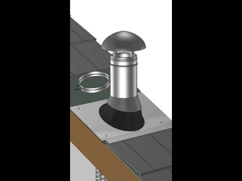
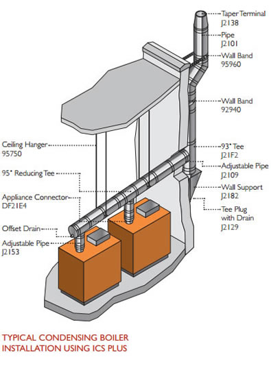
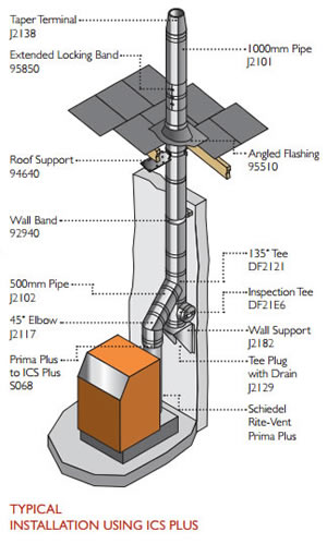
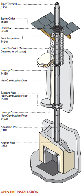
Typical installations of the ICS range will give you a brief overview of the components of the system.
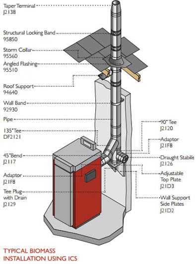
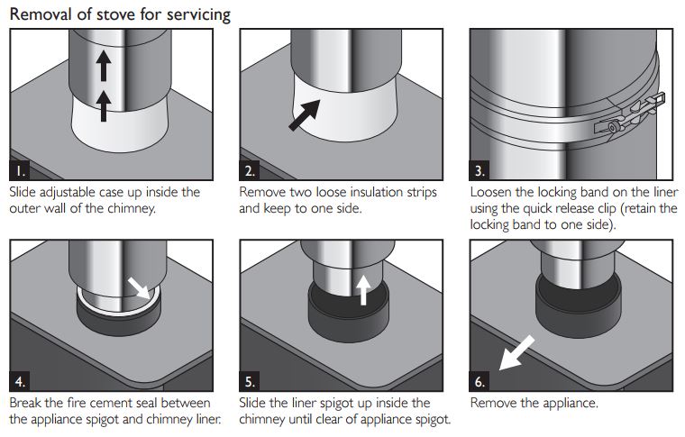
The Starter Section is available in two effective lengths: 1025mm and 600mm and is exceptionally easy to install and remove for servicing. The process for the ICS version matches the ICID version. Simply inserting a male spigot of the liner into the appliance spigot, sealing it, insulating it and then sliding down the case to cover the stove spigot. Removal for servicing and re-installation is just the reverse.
ICS Twin Wall Insulated Chimney System Installation
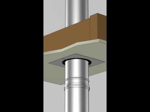
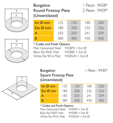
A ventilated fire stop plate is not required for single storey bungalows with a ventilated loft space. Schiedel has developed a solid fire stop kit that can be fitted even more unobtrusively in the ceiling.
The fire stops can be used with Eco ICID and ICS twin wall flues and are available in three options: one piece round, two piece round and one piece square.
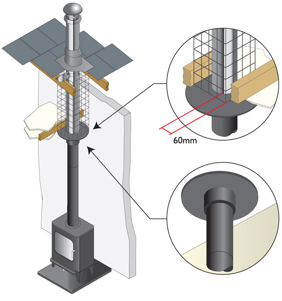
These unventilated fire stop plates may only be used on a combustible ceiling in a bungalow where there is a minimum 60mm distance to combustibles where the chimney penetrates the ceiling area and where the roof space above the ceiling is open and ventilated. Within the roof space, a protective wire mesh framework must be built around the chimney to ensure the minimum 60mm distance to combustibles is maintained.
ICS Twin Wall Insulated Chimney System Installation
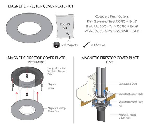
This new addition to the ventilated firestop range has been introduced an aesthetic cover plate kit, which fastens to the standard ventilated firestops using the magnets which are provided in the kit along with the cover plates. Kits are available in plain finish, painted matt black to RAL 9005, or painted matt white to RAL 9016 to match the firestops.
ICS Twin Wall Insulated Chimney System Installation
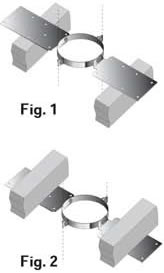 The roof support is supplied as a kit complete with two side plates for fixing to the roof trusses, a band to give lateral support to the chimney as it passes through the roof, and 3 self tapping screws, which are secured to the chimney through the band to give a load bearing capacity. When the plates are installed above the roof trusses as in Fig.1 the maximum number of pipes, which may be suspended from the roof support is 6 x 1m pipes.When the plates are attached below the trusses as in Fig.2 the maximum number of pipes, which may be suspended is 4 x 1m pipes.
Please note: It is the responsibility of the installer to ensure that the joist to which the roof support is being attached is load bearing and capable of withstanding the weight of the system being installed.